---
config:
  theme: neutral
---
flowchart LR
  subgraph old [Old Way - Dedicated Wires N²]
    direction TB
    M1["A"]
    M2["B"]
    M3["C"]
    M4["D"]
    M5["E"]
    M6["F"]
    M7["G"]
    M8["H"]

    M1 -.-> M2
    M1 -.-> M3
    M1 -.-> M4
    M1 -.-> M5
    M1 -.-> M6
    M1 -.-> M7
    M1 -.-> M8

    M2 -.-> M3
    M2 -.-> M4
    M2 -.-> M5
    M2 -.-> M6
    M2 -.-> M7
    M2 -.-> M8

    M3 -.-> M4
    M3 -.-> M5
    M3 -.-> M6
    M3 -.-> M7
    M3 -.-> M8

    M4 -.-> M5
    M4 -.-> M6
    M4 -.-> M7
    M4 -.-> M8

    M5 -.-> M6
    M5 -.-> M7
    M5 -.-> M8

    M6 -.-> M7
    M6 -.-> M8

    M7 -.-> M8
  end

  subgraph new [New Way - Packet Routing]
    direction TB

    SW1["Switch 1"]
    SW2["Switch 2"]

    Mod1["A<br/>addr"] --> SW1
    Mod2["B<br/>addr"] --> SW1
    Mod3["C<br/>addr"] --> SW1
    Mod4["D<br/>addr"] --> SW1

    Mod5["E<br/>addr"] --> SW2
    Mod6["F<br/>addr"] --> SW2
    Mod7["G<br/>addr"] --> SW2
    Mod8["H<br/>addr"] --> SW2

    SW1 <--> SW2
  end
18 The ‘Route Packets, Not Wires’ Paper (2001)
18.1 Overview
This appendix reviews William J. Dally and Brian Towles’ seminal 2001 paper “Route Packets, Not Wires: On-Chip Interconnection Networks” from DAC 2001, which proposed a fundamental shift in how we think about interconnects at any scale.
For how this same pattern appears at NoC → PCIe → Datacenter scales, see Chapter 2: L3 & Routing Trends - Big Picture.
18.2 The Paper’s Core Proposal
The problem (2001): As chips grew denser with more modules (CPU cores, memory controllers, peripherals), connecting them with ad-hoc dedicated wiring became impractical. Design-specific global wiring was complex, unpredictable, and required extensive timing iterations.
The solution: Replace ad-hoc global wiring with a general-purpose on-chip packet network. System modules communicate by sending packets to one another over the network, not by dedicated wires.
This idea evolved into what we now call Network-on-Chip (NoC), which is common practice in modern SoCs. Most multi-core processors today (ARM, AMD, Intel, Apple Silicon) use NoC architectures rather than shared buses.
The architecture:
- Divide the chip into rectangular tiles
- Each tile contains a client module (processor, memory, etc.) and a small router
- Tiles communicate by sending packets with addresses
- Routers forward packets through a structured network
- Physical wiring is shared infrastructure, not module-specific
18.3 Key Technical Insights from the Paper
18.3.1 1. Structured Wiring Enables Better Circuits
From the paper: Structured network wiring gives “well-controlled electrical parameters that eliminate timing iterations and enable the use of high-performance circuits.”
Structured wiring enables better link circuits (the intuition):
When wires are laid out in a regular, predictable way (similar lengths, controlled spacing), we can design a “standard link” circuit (driver/receiver) once and replicate it everywhere. With ad-hoc global wiring, every long wire behaves differently due to coupling and RC effects, so designers add conservative safety margins and lots of repeaters.
What this enables:
- ~100× lower switching energy on the wire: A wire is basically a capacitor; toggling it means moving charge. If the signal swing is reduced from ~1.0V to ~0.1V, the wire’s switching energy drops with V², i.e., about 100× lower dynamic energy. (Total link power won’t drop 100× because drivers/receivers also consume power, but it’s still a major win.)
- Higher speed / lower delay: The “speedup” isn’t that electrons move faster; it’s that predictable wiring lets the receiver detect transitions sooner (less RC smearing, more controlled behavior), enabling higher clock rates or deeper pipelining.
- Fewer repeaters: With a well-behaved link, signals can travel farther before needing buffering, reducing repeater count (saving both area and power).
18.3.2 2. Identity Separate from Physical Location
Conceptual shift: Each module gets a stable network address (its “identity”), independent of physical location or which wires connect it.
This is the same principle as:
- On-chip: Tile address (not which physical wire)
- PCIe: Endpoint ID (not which motherboard slot)
- Datacenter: Loopback IP (not which NIC or ToR)
18.3.4 4. Modularity Through Standard Interface
From the paper: An on-chip network defines a standard interface “in much the same manner as a backplane bus.”
Modules designed for the standard interface are reusable and interoperable—you don’t need custom wiring for each new module combination.
At datacenter scale: BGP + /31 p2p links is our “standard interface.” Any host/ToR/spine speaking BGP can plug into the fabric. No custom per-rack wiring designs.
18.4 Why the Paper Matters for Our Design
Dally & Towles articulated principles that apply at every scale:
- Structure over ad-hoc: Hierarchical addressing, structured links beat custom wiring
- Identity ≠ connectivity: Loopback IPs (like tile addresses) are stable; physical links can change
- Shared infrastructure scales: ECMP uses all paths; dedicated pipes waste bandwidth
- Standard interfaces enable modularity: BGP everywhere (like packet interface everywhere) enables plug-and-play growth
Our datacenter design is the same pattern at building scale: replace L2 broadcast (ad-hoc wiring equivalent) with L3 routing (packet network equivalent).
18.5 The N² Problem
- First: Packet routing with 2 switches = 9 wires (4 to each switch + 1 inter-switch)
- Second: N² dedicated wires = 8×7÷2 = 28 dedicated wires for full connectivity
As N grows, dedicated wiring becomes impossible. Packet routing scales.
18.5.1 Modern Example: GPU Interconnects
This same tradeoff appears in modern GPU interconnects:
NVIDIA NVSwitch (routing approach):
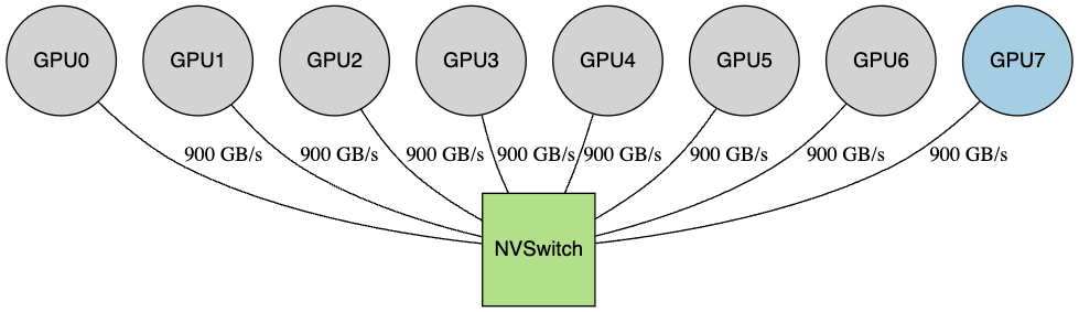
- 8 GPUs each connect to NVSwitch fabric
- NVSwitch is not a single switch; it’s a fabric built from multiple NVSwitch ASICs (e.g., 4× on HGX H100/H200-class systems; exact count varies by generation)
- This is still a clean topology: it scales by adding switch ASICs, like the “packet routing” model from Dally’s paper
AMD Infinity Fabric Direct (P2P mesh approach):
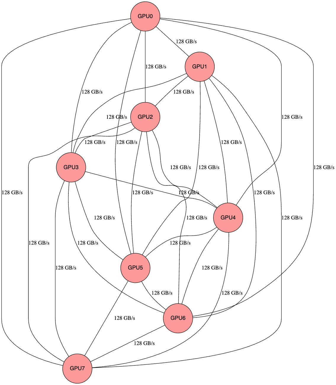
- Each GPU directly connects to every other GPU with P2P connections
- 28 direct links for 8 GPUs (N² = 8×7÷2)
- Works well for small N (a single node), but the number of direct links grows as N², so scaling beyond 8 GPUs becomes impractical
18.6 Conclusion
“Route Packets, Not Wires” isn’t just about on-chip networks—it’s a universal principle for any communication system that needs to scale.
The same lesson applies to datacenters: Don’t dedicate VLANs and L2 paths. Route IP packets with BGP over structured /31 links. Give hosts stable loopback identities. Let ECMP share bandwidth.
This paper helped establish the mental model that guides modern datacenter network design.
18.7 References
- Dally, William J., and Towles, Brian. “Route Packets, Not Wires: On-Chip Interconnection Networks”. DAC 2001.
- Dally, William J., and Poulton, John W. “Digital Systems Engineering.” Cambridge University Press, 1998.
- Seitz, Charles. “Let’s Route Packets Instead of Wires.” Advanced Research in VLSI: Proceedings of the Sixth MIT Conference, 1990.